In the main
Digging deep into graphitic corrosion of cast iron water mains

I can always say of the cast-iron water main that it is a well-tried, faithful and honest servant of the Water Engineer’ – Henry Edward Stilgoe CBE, MICE, Chief Engineer of the Metropolitan Water Board.
Cast iron is arguably the wonder material of the Victorian era, valued for its strength, affordability and versatility. It enabled major railway and architectural advances, and was widely used in developing urban water and sanitation networks for the manufacture of pipes, joints and valves due to its ability to form large, complex shapes. Three ‘generations’ of pipe casting technology were used to manufacture both distribution and trunk mains – see box-out below.
A branching network
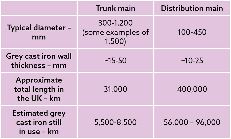
The term ‘trunk main’ comes from the hollowed elm logs used by the New River Company to bring fresh water into London in the 17th Century. Cast iron is the material that has seen the greatest use for both the large trunk mains transporting water between the major hubs, such as reservoirs and water treatment works, and the smaller distribution main transporting water locally.
Notes:
The size of trunk and distribution mains varies between companies – in some cases, what is used as a small trunk main in one place is a large distribution main elsewhere.
Total quantities aggregated from the Water Services Regulation Authority data.
Wall thickness will be dependent on casting technology, production quality and similar factors.
From around the 1820s onwards, pipes were horizontally cast in sand moulds – an approach that could lead to casting and other defects in the upper surfaces. The adoption of vertical casting helped eliminate such issues but could not ensure uniformity of wall thickness, which was solved by the introduction of centrifugal casting methods.
Grey cast iron continued to be used for pipe manufacture for many decades until ductile iron took over in the early 20th Century. Since then, materials such as epoxy-coated steel, glass-reinforced plastic, reinforced concrete and polyethylene have all been used for pipe manufacture.
However, in many urban areas, grey cast iron pipes carry the water we consume for the greatest part of its journey from the treatment works to our homes.
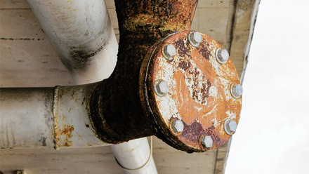
From an asset management perspective, the grey cast iron within water networks is both a blessing and a curse. Victorian investment in capacity and infrastructure has proven to be remarkably robust, with some pipes still in good condition after more than 150 years in service. Elsewhere, degradation has been extensive, with some pipes seemingly held together by corrosion products and the surface accretion of stones and soil.
Managing this infrastructure is complex, as degradation varies due to factors including cast iron composition and microstructure, soil type and local environment. The extent of corrosion can vary around the circumference and along the length of a given pipe section.
When sufficiently degraded, a pipe may allow through-wall water leakage or may burst under normal service loadings. While the impacts of distribution main failure are generally localised, trunk main failure can significantly disrupt water supply to customers and adversely impact surrounding properties and services.
The risk of a burst event can be reduced by replacement programmes, but rehabilitation or renewal can cost millions of pounds per kilometre. Asset managers need accurate field data and robust predictive models to assess failure risk and potential consequence, to target strategic replacements within available resources.
But what is the best way to collect such information?
Ideally, pipe condition could be assessed without excavation – either by detecting defects in the pipe through the surrounding soil, or by inspecting the wall thickness from within the water-filled pipe. Any chosen method must be cost-effective across the UK’s vast and often inaccessible pipe network, which in urban areas is frequently adjacent to other critical infrastructure.
Crucially, detection systems must reliably detect and accurately map the presence of graphitic corrosion within the pipe wall.
Pipebots assemble!
The Universities of Sheffield, Birmingham, Bristol and Leeds have developed miniature robots with sensors that can travel through pipes and check for defects autonomously.The smallest robot measures 40mm wide – similar to the size of a toy car. The bots are equipped with tiny, high-spec acoustic sensors and cameras, which enable them to navigate and detect faults freely.
A Pipebot swarm can be placed in a deployment hub and lowered into a water pipe through a hydrant by an engineer. The tiny patrollers will then explore the area, scan for faults and relay data back to the engineer above ground.
They are equipped with all-terrain legs that enable them to navigate through any difficult paths they might encounter while underground. They can also talk to each other within a short range, so they can work together to carry out tasks and problem solve.
Flaking off
However, this then begs the question of what is graphitic corrosion?
Since the 1920s, graphitic corrosion has commonly been considered to result from the presence of water at the interface between the iron matrix and graphite flakes leading to preferential dissolution of iron. Subsequently, corrosion penetrates the wall thickness leaving behind graphite flakes and a mix of iron oxides.
However, it is useful to remember Bertrand Russell’s advice: 'In all affairs it’s a healthy thing, now and then, to hang a question mark on the things you have long taken for granted.'
Graphitic corrosion has significant implications for the remaining load capacity of a pipe. Assessing the extent of corrosion, its conformation and the remaining wall thickness can help in predicting the remaining service life of an asset.
As part of a body of work investigating the failure of cast iron assets, we have undertaken a careful microstructural investigation that has encompassed scanning electron microscopy, along with energy dispersive and wavelength dispersive X-ray spectroscopy (EDS and WDS, respectively).
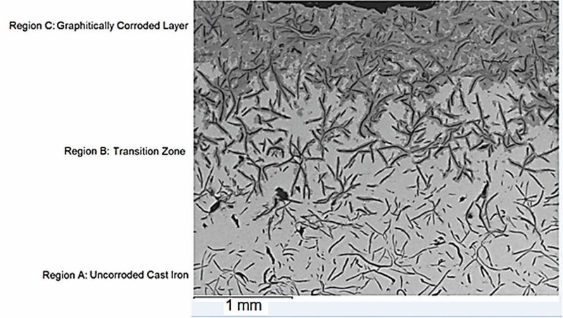
These techniques have been used to investigate samples of corroded cast iron taken from pipes that had been in service for many decades, considering regions that were i) completely corroded, ii) the ‘transition zone’ where active corrosion is taking place and iii) the uncorroded bulk metal.
This revealed that the graphite flakes are, in fact, deteriorating as part of the corrosion process. The flakes undergo a process of splitting and loss of section, with the gaps created subsequently being in-filled with complex iron oxides.
Energy dispersive spectroscopy and WDS investigations confirm the presence of chlorides at the sites of active corrosion.
Electrochemical investigations in Dr Ron Logan’s doctoral thesis – titled The graphitic corrosion of cast iron: aspects on the deterioration of trunk main – show that corrosion rates of cast iron samples in saturated soils can be as low as 6-20µm per year. However, they can exceed 1,000µm per year where the moisture in the surrounding soil water has significant levels of dissolved chloride ions.
One of the features of graphitic corrosion is that a degraded cast iron component can retain its original shape and size, i.e. there is no significant change in volume. As a consequence, even badly corroded pipework can appear (visually) to be in good condition, with original foundry markings remaining intact and legible on the surface.
This has implications for assessing in-service cast-iron trunk main, where inspection is restricted to the confines of a trench and is limited to only a part of the pipe’s total surface area.
Corrosion morphology
The local rate of graphitic corrosion can, like any other form of corrosion, be affected by the different conformations of electrochemical cells and how these interact with one another.
Given their physical size, a water main can display different behaviours in different locations on the same section of pipe, or along the overall length. It is an important observation
that significant variation in the depth of corrosion can occur over distances of a few centimetres.
Analysis of pipes taken from periods in service appear to show two different types of behaviour.
In the first, corrosion is spread over a large area of the surface in a manner reminiscent of icing on a cake. In the second, a smaller surface area corrodes but the depth of penetration is significant, and the full wall thickness may be compromised by pit-like icicles.
In terms of the degraded pipe’s mechanical performance, the two conformations observed need to be treated differently.
The presence of icing may be treated as a loss of section problem, such that the remaining section capacity (residual strength) reflects the reduced area of uncorroded metal.
By contrast, where icicles are present, it is better they are considered as cracks and treated as a fracture mechanics problem, resulting in a lower residual strength. In both cases, it is important that the depth of the transition zone is considered within any calculations.
Graphitic corrosion in cast iron pipes is influenced by many interrelated variables, making comprehensive modelling nearly impossible. One debated factor is the role of soil bacteria, particularly sulphate-reducing types. Some researchers view bacteria as the key to soil aggressiveness, while others consider soil pH and salinity to be more important.
Our findings suggest some bacteria thrive in the soil adjacent to areas undergoing graphitic corrosion, but they do not initiate the corrosion per se, nor do they control the corrosion rate within the transition zone. The ongoing debate on this topic is unlikely to be resolved given the limited support for fundamental research in the area.
Buried in the sand?
The methods used to perform non-destructive evaluation (NDE) on materials and engineered systems are diverse, and use various physical properties to assess the ‘health’ of cast iron infrastructure.
These include methods based on the magnetic and electrical properties of the cast iron, as well as the speed of elastic waves – such as ultrasound – through the material or the absorption of X-rays. Such methods rely on the detection of some level of change in the properties associated with the presence of an unexpected secondary phase – degradation due to the presence of corrosion or cracking.
Other methods for checking pipe integrity include those that ‘listen’ for leaks or a solution that bubbles when it comes into contact with, usually, leaking air. Many of these techniques are routinely deployed in the water sector and other industries, and their effectiveness is well documented and standardised.
Some well-established techniques are limited to the laboratory, as they are unlikely to be practical in the field, are regulated against, or do not consider the inherent variation in microstructure (and properties) of cast iron.
For example, while ultrasonic inspection is routine in the aerospace sector, a few millimetres of aluminium is a very different prospect from 40-50mm of (buried) cast iron with 5-10mm of graphitised material. The graphite flake structure of the metal acts to dissipate the ultrasonic signal, and the transition zone of active corrosion is strongly attenuative rather than giving rise to a clean reflection.
A significant problem for any NDE technique is accessing the structure to be assessed. With buried assets such as water pipes, inspection must rely on either exhumation to access the outer surface or, where possible, an internal assessment. Both scenarios present significant issues, particularly in the context of a trunk main.
Further, in either case, once access has been achieved, surface preparation is often required to ensure adequate measurement quality and that can lead to the asset being damaged. Any such damage may not be immediately apparent but can potentially reduce the residual life of the asset being assessed, breaking a key tenet: 'First, do no harm'.
These comments notwithstanding, ultrasonic inspection, although facing the hurdle of poor surface condition, would appear to have the best opportunity of finding the types of defects that can impact trunk main capacity.
However, significant work is required to overcome the issues that graphitic corrosion presents to meaningful data collection and interpretation.
It may be best to pair ultrasonic inspection with another technique – such as eddy current testing or magnetic flux leakage – to provide complementary results that, when combined, give a more complete picture.
It is an important observation that given the length of existing water networks and the range of soil environments in which they are situated, external NDE conducted in small excavations can only give a snapshot of the local pipe condition.
Statistical analysis can allow these data to predict the condition of nearby pipes, and asset managers can use further analysis to consider similar cohorts using data from across the network to decide about a specific pipe.
However, greater (contiguous) lengths of the network must be inspected to understand its condition fully. At present, a device capable of characterising the range of defects typically present in cast iron main at the physical resolution required does not exist.
Further developments in assessment methods, and associated data processing are needed to accurately measure key degradation features necessary to enable reliable, model-based management of water main networks.
Location, location, location
Cast iron pipes are found in water distribution networks around the world. On the one hand, this means the outcomes of research carried out in one country can inform practice in another and vice-versa. Context is key, however, and it would be unwise to simply pick up data from one source and use it uncritically.
For example, the thinner, walled, cement-lined, cast iron pipes, commonly found in countries such as Australia, are inherently more likely to undergo leakage before breaking than unlined pipes. The historic cast iron of the UK can leak from joints and even ‘weep’ through full-wall graphitisation in distribution mains, while trunk mains tend to fail before any significant leakage occurs.
There are several variables that can have an impact on overall performance. For example, in Canada, pipes will tend to be buried more deeply than in the UK, to account for the longer, colder weather, which can lead to the soil freezing. While this helps mitigate the problem of frost loading, the increased soil loading needs to be considered instead – the two things do not balance one another out.
For a number of reasons, water pipes in the UK are often located quite close to the surface. Consequently, extended periods of colder weather can lead to an increased number of failures in a given length of pipe compared with a baseline failure rate seen throughout the year.
Such winter events generally occur when the joints in a series of connected cast iron distribution pipes become corroded, preventing the normal movement of the spigot and bell joint as the pipes shrink in the cold. This means that significant tensile stresses can be generated leading to fracture from the most critical defect along the affected length.
There is a rising occurrence of summer events. These are a product of climate change, whereby longer, drier summers make soils, such as clay, more likely to shrink and crack, leading to movement of the supporting material around any buried pipes increasing the overall service loading.
Both winter and summer events are driven by seasonal changes but their likelihood of occurring is affected by local geography and associated microclimates, in tandem with ongoing degradation.
Inspecting cast iron assets in the water sector is an essential part of network asset management but remains challenging. Urban pipes are hard to access and the products of the corrosion process complicate measurement.
However, decades of research have built a solid understanding of system stresses and how corrosion affects pipe strength and strain capacity. The key challenge is accurately measuring graphitisation to enable model-based management with reliable forecasts.
Data collection can follow various paths and inform models at both local and network levels. Given the many variables and ongoing uncertainties, conservative interpretations are recommended.